Embedded Systems Assignments
Block Diagram - Team Assignment
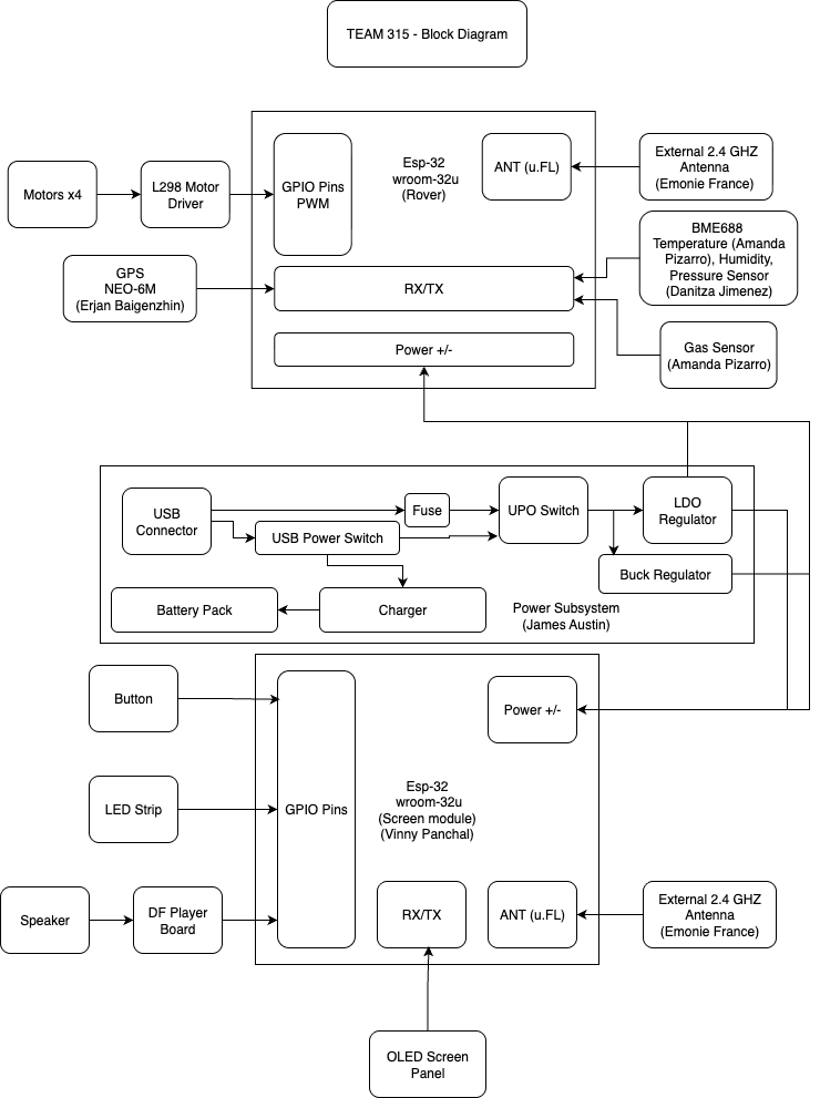
Team-level subsystem map, interfaces, and pin planning for ESP32-based platform
The goal of this assignment is to determine and document the manner in which each team member's project will communicate electronically. These diagrams clarify logical flow before code and improve overall software/hardware quality.
- A complete team-level block diagram highlighting subsystems interfacing with the ESP32.
- Clear ownership per subsystem (one owner per subsystem).
- Pin maps, bus addresses, power plan, and programming ports.
- draw.io / diagrams.net (Google Drive compatible)
- Project description example diagram
Team Block Diagram
Starting with the example from the project description and teammates' individual block diagrams, provide a detailed team-level block diagram that shows:
- Subsystem Owner for each teammate (one subsystem per member).
- Sensors connections (I²C, SPI) and any UART/GPIO lines.
- Power connection & distribution (regulators, rails, fusing, switches).
- ICSP/USB programming port routing and access.
- Pin mapping to specific GPIO/peripheral pins on each microcontroller.
- If I²C, list addresses for each peripheral; if SPI, list CS pins.
- Details of peripheral ICs (sensors, actuators, displays) directly connected.
Export your draw.io diagram as PNG or SVG and place it in
/assets/, then update the src below.
Pin Map (scaffold)
| Subsystem | Owner | MCU | Interface | Pin(s) / Addr / CS | Notes |
|---|---|---|---|---|---|
| Thermal / Smoke / CO | - | ESP32 | I²C | SDA: GPIO21 · SCL: GPIO22 · Addr: 0xXX | Shared bus w/ pull‑ups |
| OLED Display | - | ESP32 | SPI | MOSI: GPIO23 · SCK: GPIO18 · CS: GPIO5 · DC: GPIO4 | 3.3V only |
| LoRa / Mesh Radio | - | ESP32 | SPI/UART | CS: GPIO15 · IRQ: GPIO34 · UART2: RX2/TX2 | IRQ on input‑only pin OK |
| Power | - | - | - | VBAT → 5V/3.3V regs; USB‑C PD (opt) | Show fuses/switches |
Subsequent Uses of this Document
This document guides how functionality is distributed across teammates and will be updated throughout the semester as part of your public living report. It will be reviewed by external reviewers during the design review.
Checklist
- The page is easy to find (linked from landing page).
- The block diagram is clear, legible, and well‑formatted.
- Arrows show signal/power flow; buses labeled; directions clear.
- Power plan is shown (connectors, jumpers, rails, protections).
- Each teammate’s role is clearly documented with subsystem.
- Pin map, addresses, and chip‑selects are listed.